|
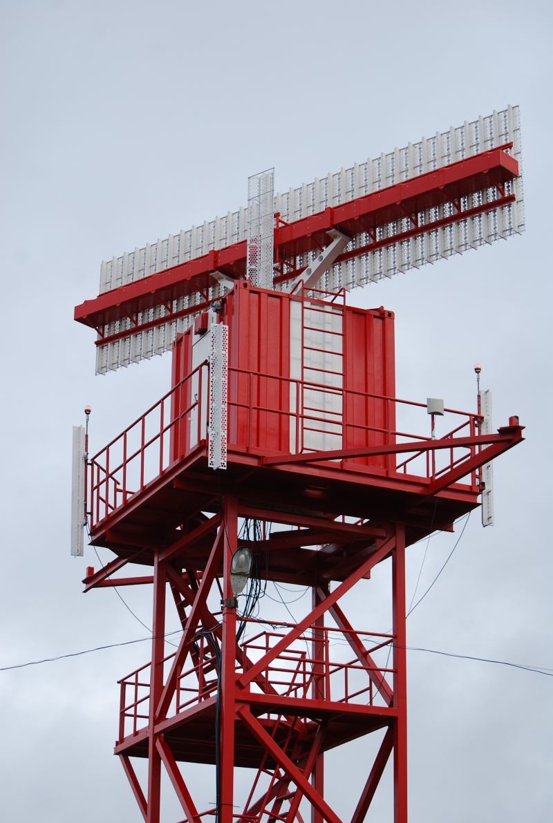
The radar incorporates both traditional RBS surveillance interrogation channel (modes 1, 2, 3/А, С, S) and separate surveillance channel – ADS-B 1090 ES thus combining customary MSSR and 4-channel ground station ADS-B 1090ES.
ADS-B 1090ES
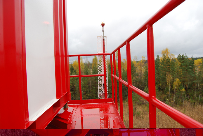
The ADS-B 1090 ES channel has a dedicated 4-sector antenna system and separate receivers that ensure surveillance of aircrafts with the antenna stopped or MSSR transmitter switched off during scheduled operations.
Aircrafts positioning accuracy is not affected by distance between them and ADS-B ground equipment. Additional comparative monitoring of MSSR data and ADS-B information regarding air targets permit verifying validity of surveillance data.
MODE S
- Using of mode S permits to increase safety of air traffic by aids of:
- Total resolution;
- Load reduction on radio channel 1090 Mhz, particularly due to ADS-B development;
- Sufficient increase in reliability of information by redundancy coding answers and requests;
- Additional information from craft, chosen altitude, maneuver indication, speed
INTERACTION WITH CONSUMERS AND OTHER DATA SOURCES
- The radar uses all known data transfer protocols including those meeting standard ASTERIX Cat 34, 48, 21,23 by ICAO
- Protocol is selected from the control terminal MSSR
- Capability to receive/transmit data via digital channels customizable from the terminal MSSR
- Unlimited capability of implementing protocols
- For standard ASTERIX categories a Protocol builder is provided that makes it possible to select only desired data elements for transmission
MONITORING AND CONTROL SYSTEM
Monitoring and control system is designed according to recent developments in this area and makes it possible to control more than 98% of components, interfaces, characteristics and MSSR parameters.
The system provides an accurate failure diagnostics or radar malfunctions and their classification.
Three more terminals can be connected. Two of these terminals can be located at any distance.
The terminals may be connected both via the telephone line by aids of DSL connections at a distance of up to 15 km and via IP router.
MSSR may be operated without permanent attendance of maintenance personnel in case the remote control is provided.
A broad range of software tools utilized by the system provides any data regarding real-time operation of radar in the form of user friendly graphs and tables, including information regarding control elements, temperatures and supply voltages of the entire radar in the form of online diagram updated in real time.
Information regarding status and operation of the radar is logged in archive so that the status may then be viewed using special visualization tools and necessary data be picked.
RECEIVER
Digital receiver warrants stability of reception channels parameters in time that ensures steady operation of the radar during the entire service life without extra maintenance.
100% repetition of receiver characteristics from item to item ensures exchangeability on the spot.
TRANSMITTER
Single-module solid-state transmitter offering high reliability.
In order to adapt the radar characteristics for operation at specific position the radar makes use of:
- Independent power adjustment in interrogation and suppression channels
- “Power map” capability – up to 32 azimuth sectors with individual power levels for interrogation and suppression channels.
Actual power emission levels in interrogation and suppression channels are measured real-time.
Status of high-frequency transmission paths of interrogation and suppression channels is continuously monitored during radar operation by power and SWR measuring.
Special software tools make it possible to capture measurement results online on the control terminal in the form of user-friendly graphs.
PLAN POSITION INDICATOR (ppi)
Captures targets of MSSR and ADS-B.
In order to ensure additional monitoring of radar operation, the display of digital target data is supported by display of analogous data received via standard Ethernet card.
Archiving and subsequent playback of records are ensured so that playback does not interfere with recording of current information.
The display systems permits connection of up to 4 test indicators three of which may be at whatever distance.
The test indicators may be connected both via the telephone line by aids of DSL connections and IP router. |